
IEPE DYNAMIC INSTRUMENTS
ICP® vs IEPE: Excitation & Circuit Guide
Understand two-wire IEPE excitation, DC bias, AC coupling, voltage headroom and triaxial channel requirements.
Request a matched configuration →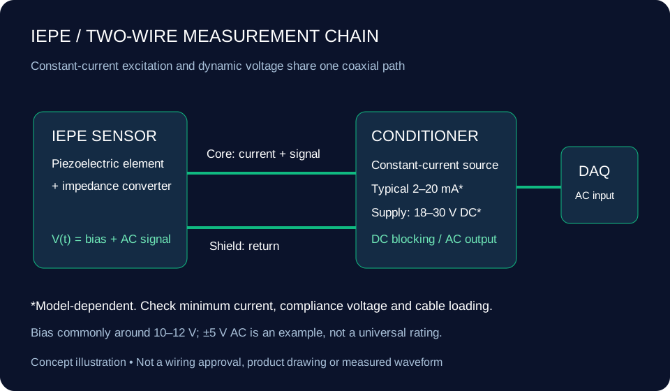
What is IEPE, and how does ICP® relate?
IEPE describes piezoelectric sensors with integrated impedance-conversion electronics. An external constant-current source powers the sensor through the same conductor that carries its dynamic voltage. ICP® identifies PCB Piezotronics’ implementation. A shared measurement principle does not establish complete interchangeability.
Separate current, supply, bias and signal swing
A typical source may offer 18–30 V DC and 2–20 mA, but those are not universal sensor ratings. Bias commonly sits around 10–12 V. The signal swings around that bias, and AC coupling removes the bias before an ordinary voltage input. Respect both the sensor’s swing and the input’s voltage limit.
Check the weakest limit in the cable and input chain
High-frequency current demand increases with cable capacitance and output voltage. Long cables may require more current than the sensor electronics alone. Insufficient compliance can clip the positive signal; the sensor electronics also need negative-swing headroom. Verify the manufacturer’s limits for your selected model.
Low-frequency response includes the sensor and the input
Review discharge time constant (DTC), the sensor’s specified low-frequency tolerance and the DAQ coupling filter together. A first-order corner is approximately 1/(2π × DTC); it is not the same as a ±5% response limit. Verify case isolation and shield grounding to avoid ground loops.
Triaxial does not mean one acquisition channel
A standard three-axis IEPE sensor has three separate signal paths and a shared return. Use three excitation/input channels and a correctly mapped fan-out cable. Do not infer pin assignments from a 1/4-28 thread alone.
NI-9234: use the actual module specifications
NI lists 2 mA IEPE excitation, ±5 V input and a maximum 51.2 kS/s per channel. Verify compliance and sensor requirements in the official specification. IEP-DAQ’s requested 102.4 kS/s profile is a separate configuration target.
References: PCB signal-conditioning basics · NI-9234 specifications · Analog Devices CN0540 IEPE interface
SPECIFICATION → CONFIGURATION REVIEW
Build your IEPE inquiry
Include the sensor, cable and acquisition input as one measurement chain. Request model-specific specifications and calibration scope with your quotation.
Selected family: IEPE excitation review
[email protected]