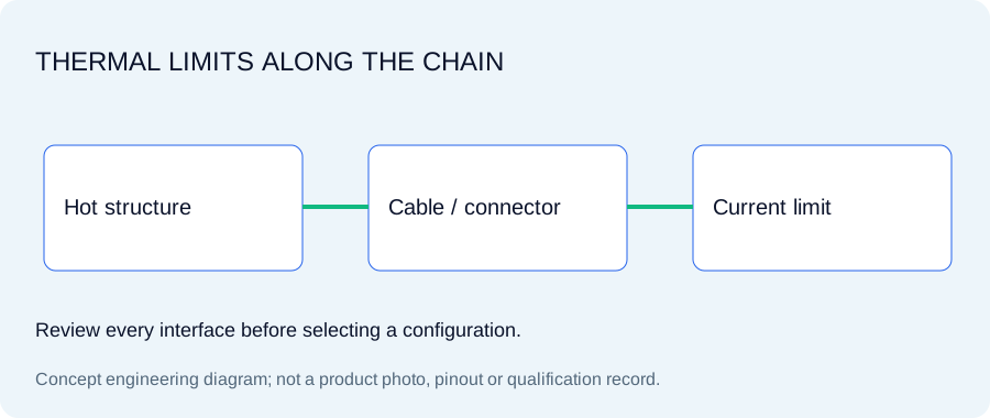
Electric-drive testing combines hot mounting points with strong electrical interference. A sensor-body temperature target does not establish the cable, connector or insulation rating. Define continuous and transient temperature, isolation test conditions and allowable current before selection.
Original concept illustration; not a released product photo or drawing.
SPECIFY THE OPERATING WINDOW
Sensitivity, interface and environmental requirements
These values describe requested configurations. Each selected model needs its own approved specifications; the targets are not one universal performance envelope.
Request >100 MΩ with test voltage and temperature stated
Cable and connector
Integral hot-zone cable or specified connector; separate thermal limits
Excitation
Do not assume 10 or 20 mA is safe at elevated temperature
Rate the hottest segment rather than the metal shell alone
Record sensor-base temperature, body temperature, connector location and cable exposure separately. Continuous operation, short transient exposure and survival temperature are different requirements. The confirmed assembly limit follows the lowest qualified component.
Check current against temperature before increasing drive
More current can support a long cable but also raises dissipation in sensor electronics. A high-temperature sensor may require reduced excitation current. An original PCB HT356B01 reference lists2–4mA; that original-model limit is not transferred to an unqualified IEP configuration.
EXACT IDENTIFIERS / ONE INQUIRY PER CONFIGURATION
Compare IEP-EVHT model requests
Select the identifier that describes your requirement, then specify accessories, documents and actual unit quantities. No identifier implies released stock or an approved cross-brand substitute.
Requested configurations · selected-model specifications and availability require confirmation
180°C is a requested body-temperature target, not an assembly rating. Confirm connector/cable limits and reduced excitation current at temperature.
Maximum-temperature request: 180°C. Released datasheet, STEP, environmental qualification and calibration availability must be confirmed for this exact configuration.
180°C is a requested body-temperature target, not an assembly rating. Confirm connector/cable limits and reduced excitation current at temperature.
Maximum-temperature request: 180°C. Released datasheet, STEP, environmental qualification and calibration availability must be confirmed for this exact configuration.
180°C is a requested body-temperature target, not an assembly rating. Confirm connector/cable limits and reduced excitation current at temperature.
Maximum-temperature request: 180°C. Released datasheet, STEP, environmental qualification and calibration availability must be confirmed for this exact configuration.
Choose a configuration, enter actual unit quantities and request the documents needed for release. Specifications, accessory fit, price and delivery are confirmed in the quotation.
Use the blank worksheet now. Request the selected configuration’s actual documents with the quote; no generic drawing or example certificate is presented as a released model record.
Motor housings, e-drive reducers and inverter-adjacent structures require a repeatable axis convention and controlled grounding. Include PWM environment, shield termination and the hottest cable segment.
A request for>100MΩ isolation needs a test voltage, temperature, humidity and measured interface. Combine this with shield/return routing and cable support. A requested isolation number alone does not prove immunity to inverter switching fields.
Resolve the interfaces before final selection
Does the IEP identifier confirm an interchangeable product?
It identifies a configuration request. Exact sensitivity, frequency response, temperature, mounting, connector pin assignment, current, bias and TEDS support require selected-model confirmation. Original model names are comparison references, not approvals.
Which calibration and engineering files can I download?
The blank engineering worksheet is available without registration. Datasheet, STEP, pinout and calibration files need the actual model release. Use the document checklist in the RFQ to request availability and scope.
How do I specify the complete quantity?
Enter the number of sensors or instruments. Each accessory line has its own quantity. Triaxial sensors consume three acceleration inputs each; force and acoustic inputs are additional. Optional budget amounts are your allowances, not quoted seller prices.