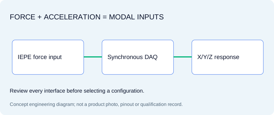
A modal frequency response function needs a force input and a response signal. An impact hammer adds a force channel; an impedance head usually adds separate force and acceleration signals. Size the input channels and select the force range independently of the response sensors.
Original concept illustration; not a released product photo or drawing.
SPECIFY THE OPERATING WINDOW
Sensitivity, interface and environmental requirements
These values describe requested configurations. Each selected model needs its own approved specifications; the targets are not one universal performance envelope.
IEP-HAM / IEP-IMP: parameters to confirm
Hammer request
IEP-HAM-500; target range ±500 lbf, sensitivity 10 mV/lbf
Impedance-head request
IEP-IMP-50; force and acceleration paths to confirm
Tip and mass selection
Request tip hardness and extender mass for the intended excitation band
Define force and response channels before selecting the kit
A force hammer requires one force-calibrated input. An impedance head measures force and acceleration through separate signal paths. Sixteen triaxial response sensors plus a hammer consume49 sensor inputs; input capacity and synchronization must be reviewed before quoting a complete setup.
Tip hardness changes the excitation, not the structural response
Harder contact and shorter contact time can extend the force spectrum, but the actual band also depends on the structure, hit, tip geometry and acquisition settings. Request a tip set and avoid double hits. No tip selection alone guarantees a valid frequency response function.
EXACT IDENTIFIERS / ONE INQUIRY PER CONFIGURATION
Compare IEP-HAM / IEP-IMP model requests
Select the identifier that describes your requirement, then specify accessories, documents and actual unit quantities. No identifier implies released stock or an approved cross-brand substitute.
Requested configurations · selected-model specifications and availability require confirmation
Choose a configuration, enter actual unit quantities and request the documents needed for release. Specifications, accessory fit, price and delivery are confirmed in the quotation.
Use the blank worksheet now. Request the selected configuration’s actual documents with the quote; no generic drawing or example certificate is presented as a released model record.
For a roving-hammer modal survey, decide which channels remain fixed and define the excitation window. With a shaker and impedance head, check stinger alignment, force path and acceleration measurement direction.
Request force calibration, acceleration calibration where applicable, overload limits, tip/force-band data, connector mapping and DAQ range. No tip hardness guarantees a fixed excitation bandwidth.
For force channels, use mV/N or mV/lbf and the corresponding calibrated force range. Acceleration channels retain mV/g or mV/(m/s²). An impedance-head record must identify both calibrations and their directions; one calibration factor cannot serve both outputs.
Resolve the interfaces before final selection
Does the IEP identifier confirm an interchangeable product?
It identifies a configuration request. Exact sensitivity, frequency response, temperature, mounting, connector pin assignment, current, bias and TEDS support require selected-model confirmation. Original model names are comparison references, not approvals.
Which calibration and engineering files can I download?
The blank engineering worksheet is available without registration. Datasheet, STEP, pinout and calibration files need the actual model release. Use the document checklist in the RFQ to request availability and scope.
How do I specify the complete quantity?
Enter the number of sensors or instruments. Each accessory line has its own quantity. Triaxial sensors consume three acceleration inputs each; force and acoustic inputs are additional. Optional budget amounts are your allowances, not quoted seller prices.