IEPEDYNAMIC INSTRUMENTS
Menu

IEP-IND / MODEL CONFIGURATION REVIEW

Industrial IEPE Vibration Sensors: MIL & M12

Build the sensor into the monitoring route.

Continuous machinery monitoring adds requirements beyond sensitivity. Set the bearing fault band, mounting thread, case isolation, ingress conditions and cable strain relief before comparing a rugged sensor with a lightweight laboratory accelerometer.

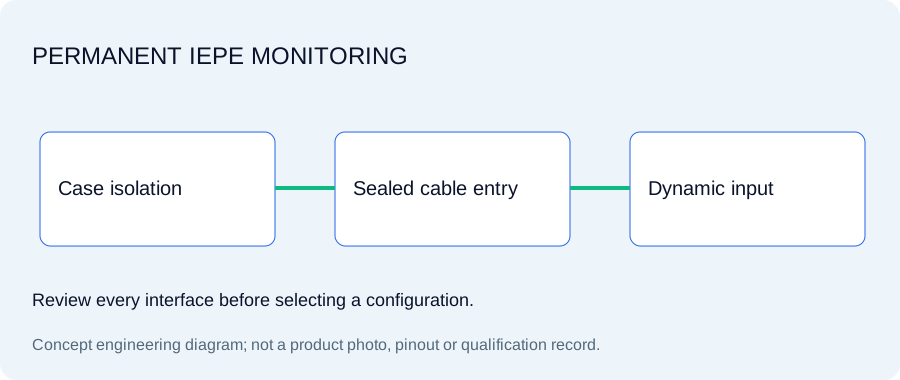
Industrial IEPE sensors: engineering concept diagram
Original concept illustration; not a released product photo or drawing.

SPECIFY THE OPERATING WINDOW

Sensitivity, interface and environmental requirements

These values describe requested configurations. Each selected model needs its own approved specifications; the targets are not one universal performance envelope.

IEP-IND: parameters to confirm
Sensitivity requests100 or 500 mV/g
Housing targetSealed stainless steel; grade, shielding and sealing to confirm
Connector requests2-pin MIL-C-5015 or M12; verify pin count and assignment
Requested measurement bandDefine low-frequency corner and upper bearing/gear band
InstallationMounting thread, isolated stud, cable support and oil exposure

Define the maintenance route before choosing a connector

For permanent installations, cable retention, replacement access and oil exposure can govern the assembly choice. A nominally compatible thread does not prove sealing or insulation after the connector is mated. Specify the connector standard, gender and strain-relief requirements.

Treat isolation and shielding as separate checks

Case isolation controls electrical connection to the mounting surface. Cable shield termination controls the return and noise path. Record both; a stainless housing or a shielded cable does not by itself prove the installed system avoids ground-loop interference.

EXACT IDENTIFIERS / ONE INQUIRY PER CONFIGURATION

Compare IEP-IND model requests

Select the identifier that describes your requirement, then specify accessories, documents and actual unit quantities. No identifier implies released stock or an approved cross-brand substitute.

Requested configurations · selected-model specifications and availability require confirmation
Request identifierMeasurement / sensitivityInterface / inputsReview & request
IEP-IND-100-MILIndustrialConfirmation requiredAcceleration
100 mV/g1 axis · TEDS: optional
MIL1 input per unit
Review IEP-IND-100-MIL

Confirm the exact pin map, stud thread, case isolation, sealing conditions and permanently installed cable route.

Released datasheet, STEP, environmental qualification and calibration availability must be confirmed for this exact configuration.

Review calibration evidence →
Configure RFQ →Add to project →
IEP-IND-100-M12IndustrialConfirmation requiredAcceleration
100 mV/g1 axis · TEDS: optional
M121 input per unit
Review IEP-IND-100-M12

Confirm the exact pin map, stud thread, case isolation, sealing conditions and permanently installed cable route.

Released datasheet, STEP, environmental qualification and calibration availability must be confirmed for this exact configuration.

Review calibration evidence →
Configure RFQ →Add to project →
IEP-IND-500-MILIndustrialConfirmation requiredAcceleration
500 mV/g1 axis · TEDS: optional
MIL1 input per unit
Review IEP-IND-500-MIL

Confirm the exact pin map, stud thread, case isolation, sealing conditions and permanently installed cable route.

Released datasheet, STEP, environmental qualification and calibration availability must be confirmed for this exact configuration.

Review calibration evidence →
Configure RFQ →Add to project →

MODEL + INTERFACES + MATCHED ACCESSORIES

Request your complete measurement chain

Choose a configuration, enter actual unit quantities and request the documents needed for release. Specifications, accessory fit, price and delivery are confirmed in the quotation.

[email protected]

1 units × 1 inputs = 1 sensor inputs. Other channels are additional.

Confirm the exact pin map, stud thread, case isolation, sealing conditions and permanently installed cable route. TEDS: optional.

Matched accessory requests

Quantity is per line. Conditioner and calibration upgrades are optional. Enter your own planning allowance only if useful; blank amounts remain unpriced.

Engineering documents to request

Selected-model release files and certificate availability must be confirmed. This checklist does not imply that they already exist.

Optional planning allowances & budget

Known allowances: USD 0.00 · 3 unpriced lines.

Buyer-entered planning figures, not seller pricing. Freight, tax and other unpriced work are excluded.

Open prefilled email →

Review the complete request brief
IEPE Dynamic Instruments — configuration inquiry
Name: 
Company: 
Reply email: 
Requested model: IEP-IND-100-MIL
Configuration: IEP-IND; Acceleration
Requested sensitivity: 100 mV/g
Catalog sensitivity target: 100 mV/g
Connector request: MIL
Pin assignment request: To confirm
Host DAQ / input: Not supplied
Sensor / instrument quantity: 1 units
Input channels required: 1 (1 per unit; other channels excluded)
Original model: Not supplied
Submission page: /
Originating page: /
Model evidence: Configuration request; selected-model specification and availability require confirmation.
Accessory request lines:
- IEP-CBL-MIL: MIL sensor cable assembly; quantity 1; buyer allowance each not supplied; Confirm pinout, shielding, length, oil exposure and mating plug.
- IEP-MAG-35: Flat/curved magnetic mounting base; quantity 1; buyer allowance each not supplied; Request holding-force conditions; mounted resonance and bandwidth need separate review.
Document requests: Selected-model datasheet; Calibration method, traceability and uncertainty
Buyer model allowance each: not supplied
Buyer target total budget: not supplied
Known planning allowances: USD 0.00; 3 unpriced lines. Buyer-entered estimates only; not a quotation or savings guarantee. Freight/tax/other unpriced work excluded.
Project requirements:
Please confirm selected-model specifications, compatible interfaces, document availability, formal pricing, payment terms and delivery in the quotation.

Engineering files: check the exact model release

Use the blank worksheet now. Request the selected configuration’s actual documents with the quote; no generic drawing or example certificate is presented as a released model record.

Selected-model release required

  • Datasheet and usable-response curve
  • Released STEP and dimensional / mounting drawing
  • Mating-view pinout and axis drawing
  • Calibration certificate and applicable scope
  • TEDS readback and environmental evidence
Review calibration and traceability requirements →

Match the measurement to the test structure

Wind turbines, pumps, compressors and gearboxes need repeatable mounting and a maintainable cable route. State whether measurements are temporary surveys or continuously connected channels.

Review an original model →

Evidence to request before ordering

Require the actual ingress test conditions, connector/pinout drawing, insulation measurement, frequency response and temperature derating for the selected model.

Define the calibration scope →

Specify diagnostic frequency rather than a generic wide band

Bearing and gear measurements may need high-frequency response while machine-speed trends need a stable low-frequency baseline. Include both ends of the useful band, peak level and the receiving input. Magnetic mounting can change the upper usable response.

Resolve the interfaces before final selection

Does the IEP identifier confirm an interchangeable product?

It identifies a configuration request. Exact sensitivity, frequency response, temperature, mounting, connector pin assignment, current, bias and TEDS support require selected-model confirmation. Original model names are comparison references, not approvals.

Which calibration and engineering files can I download?

The blank engineering worksheet is available without registration. Datasheet, STEP, pinout and calibration files need the actual model release. Use the document checklist in the RFQ to request availability and scope.

How do I specify the complete quantity?

Enter the number of sensors or instruments. Each accessory line has its own quantity. Triaxial sensors consume three acceleration inputs each; force and acoustic inputs are additional. Optional budget amounts are your allowances, not quoted seller prices.